![]()
“OpenSesame” is a curatin automation system I developed to allow my existing home automation infrastructure to control my curtains. Due to the size and nature of the curtain rods I have installed, I found the existing solutions either physically incompatible, or the provided software would not integrate properly with my Google Home system.
OpenSesame is comprised of a physical product design, an electronics design, and a software package, all rolled together to allow easy and automatic opening and closing of my home’s curtains.
Features
- Easy to install - fits nearly any kind of curtain rod and curtain pairing.
- Unobtrusive - can be hidden behind the top side of the curtain to hide the motor.
- Adjustable - included in the physical design is an adjustable tensioning system on the idler side of the looped “drive string”.
- Robust and reliable - the electronic and physical design utilizes a strong stepper motor along with a zero-backlash worm gear to ensure the system always knows its position, without the need for end-stops or limit switches.
- Quiet - a TMC2208 or TMC2209 stepper driver is used in the current design to allow quiet, reliable operation.
- Updatable - the firmware I developed for the ESP32 microcontroller driving the electronics has an “OTA” firwmare update feature, allowing the system to be updated with no user intervention.
Physical Design
The design is based on the concept that a loop of chain driven rotationally around a track will have equivalent motion in opposing directions. This allows bilateral curtains to be easily opened with a single motor.
For simplicity and aesthetics, I opted to use white #10 bead chain – a common material used for other residential blinds and window treatments. This is looped around a notched drive-wheel and an un-notched (smooth) idler wheel on the opposing side of the window. The notched drive-wheel is driven by a worm gear, which is paired to a spiral shaft driven by a NEMA-17 stepper motor. The worm gear operates at a 26-to-1 reduction ratio.
The worm gear and stepper motor allows the system to have both ample torque and to reliably position itself without the need for end-stops or homing switches. Explained more below, an initial starting position (curtains in a closed position) is set, and the current position of the motor is tracked and saved by a control server. This allows it to maintain a known position even through power cycles. The stepper motor is driven by a Trinamic driver IC with “Stealthchop” operation enabled, greatly reducing the noise typically produced by stepper motors.
The bead chain is cut to an appropriate length, and joined with a small plastic clip, placed in the center of the bead chain. The chain is tensioned on the idler side. The idler wheel is fixed to a carrier which “floats” on a horizontal track. This carrier has embedded nuts, which allows its horizontal position to be adjusted by 30mm M3 screws. The screws are offset to ensure no interference with the idler wheel, even when fully tightened. This 30mm of adjustment length allows the system to be easily tensioned, even when the bead chain is oversized.
Electronics
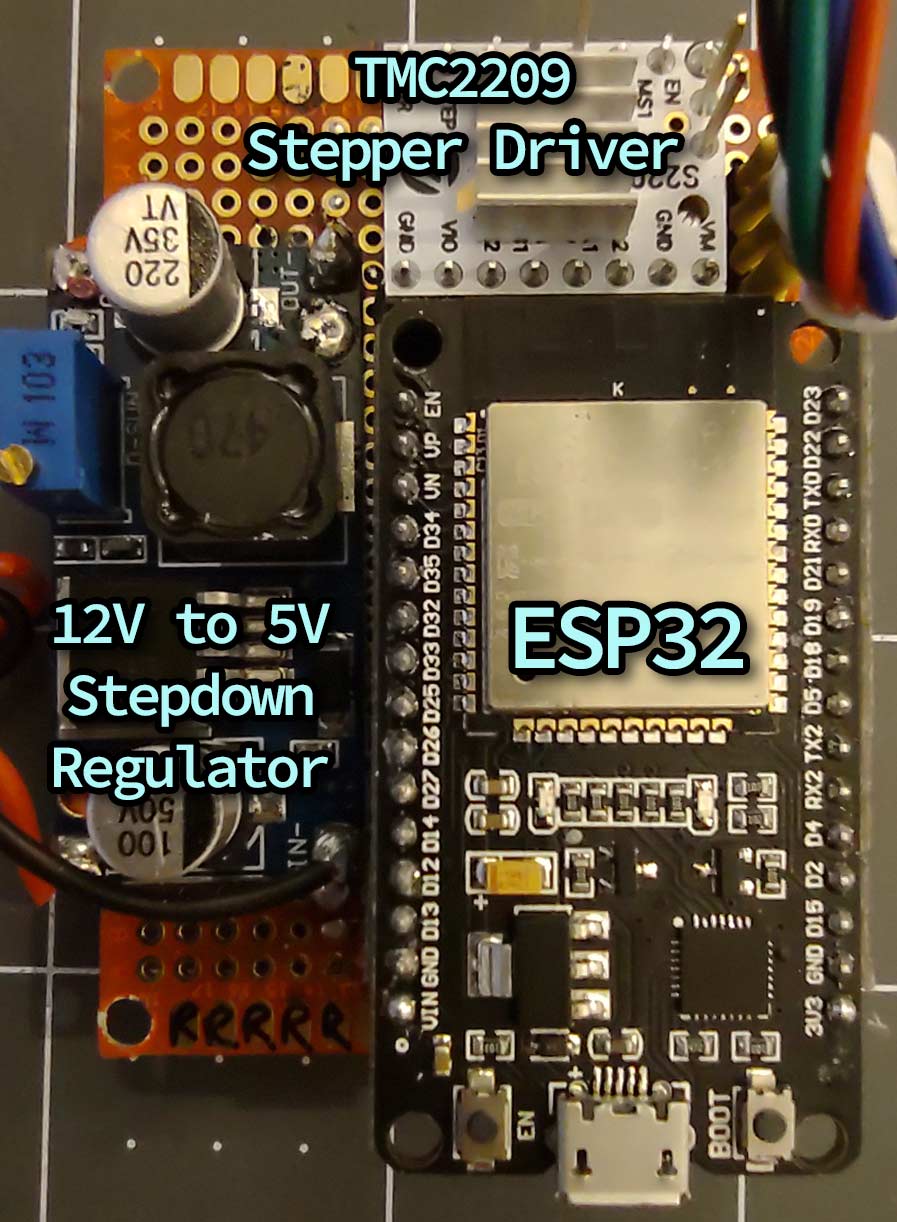
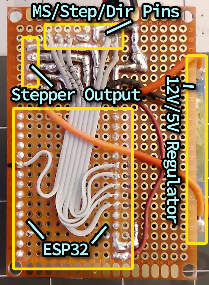
The electronics design is founded on an ESP32 IoT microcontroller. This is interfaced with a TMC2208 or TMC2208 for silent stepper operation, though a cheaper A4988 driver is also compatible. Powering the system is a standard “wall-wart” 12V/2A DC power supply. This 12V is fed directly into the motor-supply side of the stepper driver, and then into an embedded 12V -> 5V stepdown regulator, which powers the logic-side.
The physical layout of the electronics was determined primarily by the 50mm x 70mm perf-board used to secure the components. The power regulator is soldered directly to the board to keep it secure, with the underside protected by Kapton tape. All components with the exception of the power regulator are socketed to make it easy to replace or swap components.
Board Front

Board Back

Software
The ESP32 connects with a local WiFi network, where it hosts an asynchronous HTTP server. This server listens for standard requests, where it parses command requests, and responds with the active status of the system (configuration status, target position of stepper, and current position of stepper).
This HTTP server allows for easy integration with nearly any kind of home-automation software which allows for web-hooks to be used. It even provides use for cloud-based solutions if the ESP32 HTTP server’s port (8888) is opened/forwarded through your local firewall. Services compatible with this approach includes IFTTT, Home Assistant, or even Google Home.
In my own home I have set up a custom Flask server which integrates with Google Assistant’s Smart Home API. This allows me to create custom devices and device descriptors for any kind of home devices (even my greenhouse), and use local webhooks to allow control of these devices. A guide on how to do this can be found here.
For simplicity, there are no limit or homing switches in the physical/electrical design. While the TMC2209 is capable of sensorless homing, I have employed a different kind of consistent positioning method which is capable of remembering the position of the curtains across power cycles. The current position of the system is tracked and saved (on disk) on a separate local server which interfaces with the Google Home/Automation backend. On startup/boot, before the ESP32 allows the system to be moved, it requests that the server send the last measured/saved position reported by the ESP32. This initializes it back to its state prior to power cycling.
This approach was chosen over storing the position in the ESP32’s EEPROM due to the low write-cycle lifespan of the ESP32’s emulated EEPROM. The ESP32 design mimics EEPROM by partitioning some of the SPI flash storage for this purpose. Unfortunately these SPI flash chips generally have a write-cycle lifespan of around 10,000 cycles. Assuming curtains are opened and closed 2-4 times per day, and that the last known position is saved after an open- or close-cycle, this would give the system a 3-5 year lifespan. My local server’s NVMe storage, however, has significantly more endurance.