
RHEG — Rigid Harmonic Epicyclic Gearing, is a mechanical gearing system inspired by “Harmonic Drive” or Strain Wave Gearing (SWG) systems. It achieves incredibly high and reliable gear reductions in a very small footprint, while improving strength and reliability characteristics of the output mechanisms. Unlike Strain Wave Gearing, RHEG is designed to be suitable for rapid-prototyping and 3D printing, without compromising on the reliability of the mechanism.
About
RHEG is a fully 3D-printable gearing system capable of incredibly high gear ratios, reliable performance, and an exceptional (for being 3D printed) gearbox efficiency.
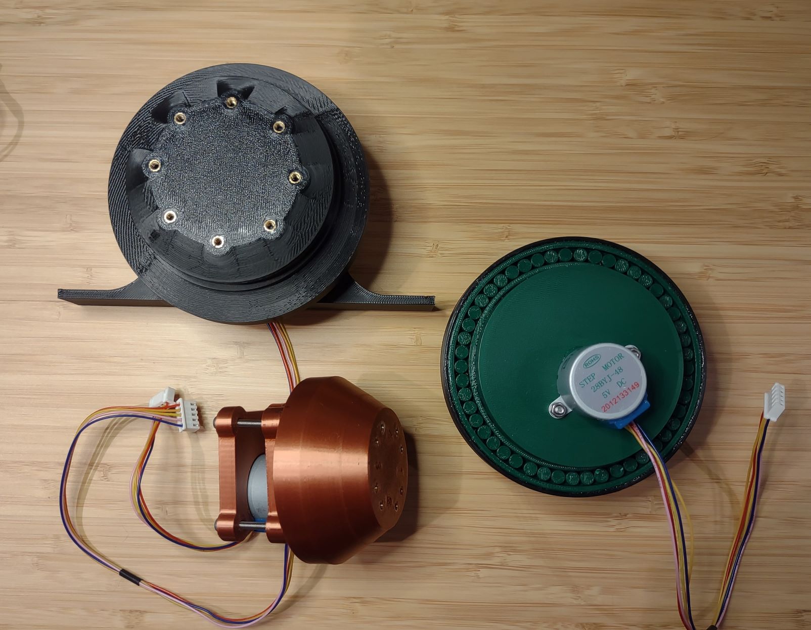
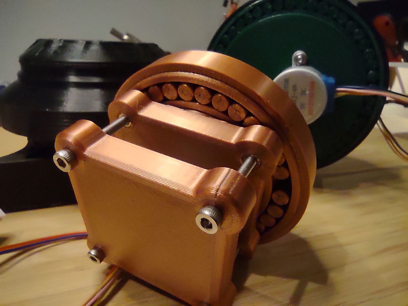
- RHEG incorporates the use of my MashedBearings parametric roller bearing generation system, allowing the entire system to be 3D printed. Everything was printed on a consumer-level FDM printer, excluding the stepper driver.
- The stepper motor used by RHEG is one of the cheapest, commonly available stepper motors. The 28BYJ-48 stepper motor used in this application cost under $2.
RHEG vastly expands the range of potential uses for this cheap 28BYJ-48 motor. It is no longer restricted to applications requiring very low torque, and can be used to move, operate, or open heavy doors/hatches, to drive other systems requiring slow, consistent, but heavy torque/loads, or any other related application.
Features
- Excluding the stepper motor, it is fully 3D printable on a standard, consumer-grade FDM printer.
- It uses one of the most inexpensive stepper motors available (28BYJ-48), making it cheap and easy to implement in a variety of applications, without hitting the wallet.
- It packs incredibly high gear reductions in a very small package, and can be parametrically adjusted to provide a variety of output torques and speeds.
- The internal mechanism is simple and reliable. Unlike strain wave gears, it does not rely on compliant or flexible mechanisms, which are likely to fail over time.
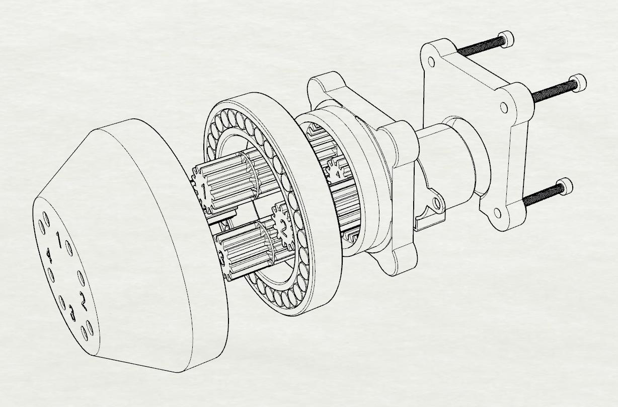
How Does It Work?
The core of the system are the four dual-sided planetary gears, acting as a collective carrier gear coupling the input sun gear to the output annulus. This collective carrier is divided vertically into two segments, each with a different number of teeth. It is the harmonic between the difference in teeth count which determines the output ratio.
The gear ratio can be calculated with the following:
Output = (Tc / Ts) * (To / (Ta - To))
Where:
Tcis tooth count of the collective carrier (sum of input planets)Tsis the tooth count of the input sun gearTais tooth count of the input/stationary annulusTois the tooth count of the output annulusTamust not equalTo
Take for example the small RHEG in the pictures below. It has 13 teeth on the input sun, 13 teeth on each of the 4 planetary gears (52 collective) 39 teeth on the input annulus, and 38 teeth on the output annulus:
Output = (52 / 13) * (38 / (39 - 38))
Yielding a gear ratio of 152.
The output ratio can be parametrically adjusted by modulating the difference between Ta and To. For instance, if To was 37 in the example above, the output ratio would be reduced to 76.
Tests & Results

An example of the test platform used to evaluate the gear systems is shown above. The motor and RHEG system is fixed to a stationary platform. Into this an 8mm steel rod is fixed to the output annulus of the RHEG system. At the end of this steel rod, a tapered holder is used to support a bucket of known mass at a known distance from the center of rotation.
As a starting position, the RHEG system and motor were set to a horizontal configuration. This ensures that the force vector defining the applied torque is perfectly orthogonal to the gear system. The applied force is at a distance of +346.67mm from the center of rotation. The applied torque of the rod (mass adjusted by its COM) was also factored in to the results.
Mass was measured and added to the bucket. The motor controller (ESP8266 and A4988 stepper driver) was then used to drive the motor ‘up’ to +10 degrees (CCW), and then back ‘down’ to +0 degrees starting position (horizontal).
The large RHEG system was able to lift both the weight of the rod and an additional 1025 grams at +346.67 mm! When the applied torque of the rod is added, this is equivalent to 3.762 NM or 2.775 ft·lb of torque!
The small RHEG system was capable of lifting both the weight of the rod and an additional 902 grams at the same +346.67mm distance.
Given that the datasheet for the 28BYJ-48 stepper driver notes it is rated for 300 gf·cm (0.03 NM), the large RHEG system provides an effective torque multiplication factor of x125.4! Given the ratio of this large RHEG system is 185, this equates to a torque conversion or gearbox efficiency of 67.8%.
These results are quite impressive, especially considering that the entire RHEG system tested in this setup was 3D printed, including the roller bearings. The only hardware used were a few M3 fasteners and brass inserts, and the 28BYJ-48 stepper motor itself!
Video/Pictures
Design Process & Tools
The following tools were used in the design and production stage of these example RHEG systems, and in the deployment of this page:
Software:
- Rhinoceros 3D
- MashedBearings plugin for Rhinoceros 3D
- Plugin developed with Microsoft Visual Studio 2019 and .NET Framework 4.8
- Arduino & VisualMicro (MCU firmware)
- PrusaSlicer 2.3.1
- OctoPrint + MeatPack
Hardware:
- Prusa MK3S+ and MINI+ 3D Printers
- eSun PLA+ and Duramic PLA+ filaments
- M3 socket-cap fasteners (10-20mm)
- M3 heat-set threaded inserts
- 28-BYJ48 stepper motors (generic)
- A4988 stepper drivers (generic)
- ESP8266 microcontroller (generic)
- Cyanoacrylate glue (thick) for fixing input and output annuli to roller bearing
Print Parameters:
- 0.20 mm layer height
- 4 vertical shells
- 6 horizontal (top/bottom) shells
- Generic PLA/PLA+ filament profile, with increased retraction to prevent stringing
- Gap filling set to 200% threshold
- Printed on “Satin” and “Textured” spring-steel sheets
Process:
The design process was fairly straight forward. The design was first broken into principal components, such that each could be tested in isolation. For instance, the input stage of the sun, planet, and input annulus were tested first, before creating an integrated final unit.
Each component part was drawn, designed, and modeled in CAD. The pieces were virtually assembled, and adequate clearances were added to make the final STL meshes suitable for FDM printing.
After the design was completed and verified in CAD, the NURBS/BREP polysurfaces were meshed into high resolution STL files. These were subsequently sliced in PrusaSlicer using the parameters noted above, and printed.
The parts were then assembled, fit and clearances were verified, and then final assembly was made with CA adhesive where needed (roller bearing races). Before final gluing, grease was packed into all moving components.
The testing protocol detailed above was then used to validate final product specifications.
Where to get it?
The example presented here will be publicly available, but I am also working on expanding the MashedBearings plugin for Rhino3D so that this gearing system can be parametrically adjusted to provide a number of sizes, ratios, and output speeds.